top of page

Analysis
Analysis: Welcome


Frame Construction
Suspension Arms
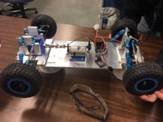
Completed RC Car- Design 1
Analysis: Services

Requirements:
-Support the weight of the drive train
-Must be able to compete in all ASME RC Baja competition events
-RC car must meet a max weight of 10 pounds
-Have a turning diameter less then 6 feet
-Must be able to drive in different types of terrain
One requirement is that our RC car must turn at a radius of less than 3 feet. For this requirement this directly relates to the control arms. The control arms help the car have traction so the wheels can be steered. When designing the control arms there were many parameters that had to be calculated with specific conditions. The length of the control arms directly impacts the length of the axial and turnbuckles. After finding the length of the control arms, the thickness was found next that would be able to withstand the force of a 2 foot drop. Since the design for the chassis plate was first, it made it possible to find the weight and find the amount of force the suspension will have to support which can be found in the appendix. After a two foot drop the suspension needs to support 157 newton pounds. This calculation used max stress and a section equation to find the thickness. Using the same technique to determine how much force the control arms need to support when the RC hits a wall at top speed. My calculations can be found in the appendix. To withstand a force of 82 newton’s the control arms need to have a thickness of 270 nanometers and a max of 5 millimeters. After calculating the dimensions of the control arm, a calculation was necessary to find the angle the control arms need to attach to the frame. Using geometrical calculations, the angle has to be at least 17 degrees. From a different mathematical approach, the turning radius was found which can be found in the appendix. Using the length of the axial and the smaller length of the servo connecting rod my calculations were able to find that our car will have a turning radius of 2.9 feet which is in the 3 foot parameters.
Another requirement is that our RC car must travel over different types of terrain. For this requirement this is directly proportional to the alinement and having a small amount of stress on the axle and drive cups. In order to minimalize the stress adjusting the shock absorbers and the tire rods would assist with this. When designing the shock absorbers there were many parameters that had to be calculated with specific conditions. The angle of the shock absorbers directly impacts the control arms and the amount of stress on the axle as well as the turning radius. A lot of things are impacted by the angle of the shock absorbers and a lot of calculations are made for these different conditions.
The amount of travel the chassis must travel will also impact the amount of force the suspension will absorb. When competing our RC car, the product must be able to support its weight while navigating over hills and other obstacles. At the current design the product does not have much room for travel. An idea to work out this problem is to move the tire rods further down the mounting part. Having the tire rods parallel to the suspension arms would maximize the amount of travel and the chassis plate would have more mobility. The shock absorbers can also be moved to give them a larger impact on the suspension arms. A bracket can me bolted to the top of the shock mount that can then be connected to the shock absorbers at a smaller angle which would put more force on the springs. That’s a good thing.
Analysis: About Me

Analysis: Image
Contact Me

Analysis: Contact
Analysis: Blog2 Custom Feed
bottom of page